Create your own dX: Overengineered Electronic Die
Make your own dX: Overengineered Electronic Die! Here is how I made the first version using an Adafruit Trinket. (I have since made a second version using a custom PCB and a third version adding a piezo sensor.)
I used the following things:
- A standard or relatively-standard Arduino board.
- An Adafruit Trinket 3.3v board.
- An Adafruit Mini 8x8 LED Matrix w/I2C Backpack in any color.
- Three very tall tactile button switches.
- One slide switch.
- A JST extension cable to cut in half to use as the battery connector.
- A 3.7v 150mAh Li-Poly battery.
- Hookup wire, the smaller the gauge the better.
- Heat-shrink tube.
- A breadboard.
- A bunch of wires for breadboarding.
- A 10μF capacitor.
- Two 5-pin male headers.
- A piece of foam (the LED matrix comes inserted into it).
- The Adafruit Arduino 1.0.5 software.
- The dX firmware for the Adafruit Trinket.
- The dX Enclosure for Adafruit Trinket from Shapeways.
Programming
The dX code is just a couple hundred bytes shy of the 8K of total flash memory in the ATtiny85. There isn't enough room for both dX and the bootloader that Adafruit installs on the Trinket. We'll have to overwrite the bootloader, so we can't use the USB port: we'll have to program the ATtiny85 directly, using an Arduino as an ISP. This makes things a heck of a lot more complicated. Fortunately, the process is fairly straightforward once you get past the 20 or so steps required. :)
- Download and install Adafruit Arduino 1.0.5.
- Locate and open the boards.txt file in hardware → arduino → boards.txt.
- Add the following to the end of boards.txt, after the existing Adafruit Trinket entries:
- Launch the modified Adafruit Arduino 1.0.5.
- Open the ArduinoISP sketch from File → Examples → ArduinoISP.
- Connect your Arduino to your computer.
- Select your model of Arduino (or a compatible model) from Tools → Board → <model name>.
- Select the port corresponding to your Arduino from Tools → Serial Port → <port name>.
- Make sure the programmer is set to Tools → Programmer → AVRISP mkII.
- Upload the ArduinoISP sketch to your Arduino. (When I first tried this, I got a
java.lang.NoSuchMethodError: gnu.io.CommPortIdentifier.openerror. My solution was to use Arduino 1.5.5 instead, just for this step. This is not Adafruit's fault; the official Arduino 1.0.5 has the same issue.) - Disconnect the Arduino. (We're going to be hooking things up to it.)
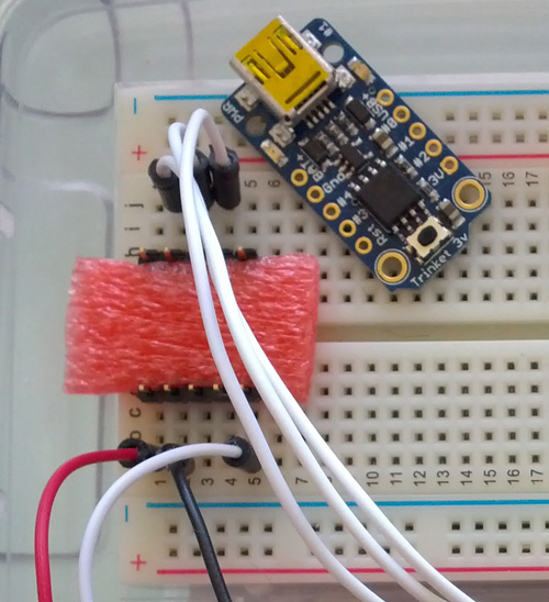
- Insert two 5-pin male headers about half-way (not all the way!) into the breadboard and stick a piece of foam between them. The foam spreads the headers apart and ensures a good connection with the Trinket.
- Place the Trinket on top of the headers. You'll have to squeeze the headers together as you do this. (If you don't have to squeeze, either the headers are too far in or the foam is not wide enough, and you won't get a good connection. Make sure you have to squeeze!)
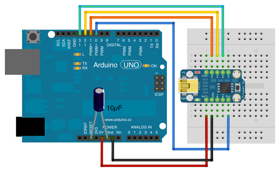
- Wire the Arduino to the Trinket. Connect Arduino pin 13 to Trinket #2, Arduino pin 12 to Trinket #1, Arduino pin 11 to Trinket #0, Arduino pin 10 to Trinket RST, Arduino 5V to Trinket BAT+, and Arduino GND to Trinket GND. Add a 10μF capacitor between Reset and Ground on the Arduino (not on the Trinket!). Make sure the side with the − stripe is the one connected to Ground.
- Download and open the dX_trinket sketch. (Now we're finally getting somewhere!)
- Connect your Arduino to your computer (again).
- Change the board setting to Tools → Board → Adafruit Trinket 8MHz (No Bootloader). This is the option we added in step 3.
- Change the programmer setting to Tools → Programmer → Arduino as ISP.
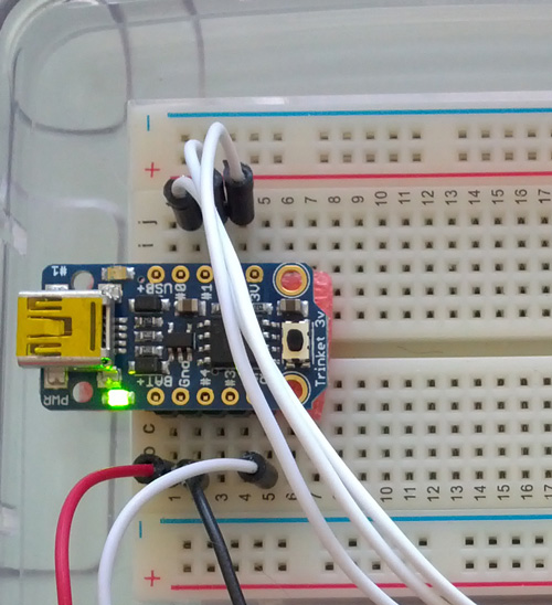
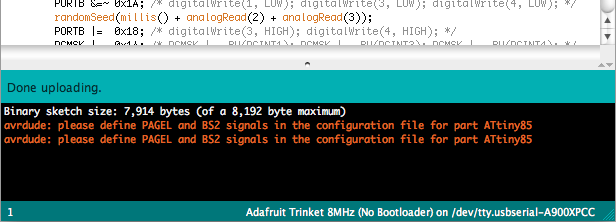
- Upload the dX sketch. The Arduino and the Trinket should flash red LEDs at each other for a while, then you should see the "Done uploading" message. If you see a message about
avrdude: please define PAGEL and BS2 signals, you can safely ignore it. If you see any other errors, make sure the Trinket is secured to the headers on the breadboard and that your wiring is done correctly. - Pop the Trinket off the breadboard. You're done with programming; on to wiring!
trinket3-nb.name=Adafruit Trinket 8MHz (No Bootloader)
trinket3-nb.bootloader.low_fuses=0xF1
trinket3-nb.bootloader.high_fuses=0xD5
trinket3-nb.bootloader.extended_fuses=0xFE
trinket3-nb.upload.maximum_size=8192
trinket3-nb.build.mcu=attiny85
trinket3-nb.build.f_cpu=8000000L
trinket3-nb.build.core=arduino:arduino
trinket3-nb.build.variant=tiny8

trinket5-nb.name=Adafruit Trinket 16MHz (No Bootloader)
trinket5-nb.bootloader.low_fuses=0xF1
trinket5-nb.bootloader.high_fuses=0xD5
trinket5-nb.bootloader.extended_fuses=0xFE
trinket5-nb.upload.maximum_size=8192
trinket5-nb.build.mcu=attiny85
trinket5-nb.build.f_cpu=16000000L
trinket5-nb.build.core=arduino:arduino
trinket5-nb.build.variant=tiny8
Wiring
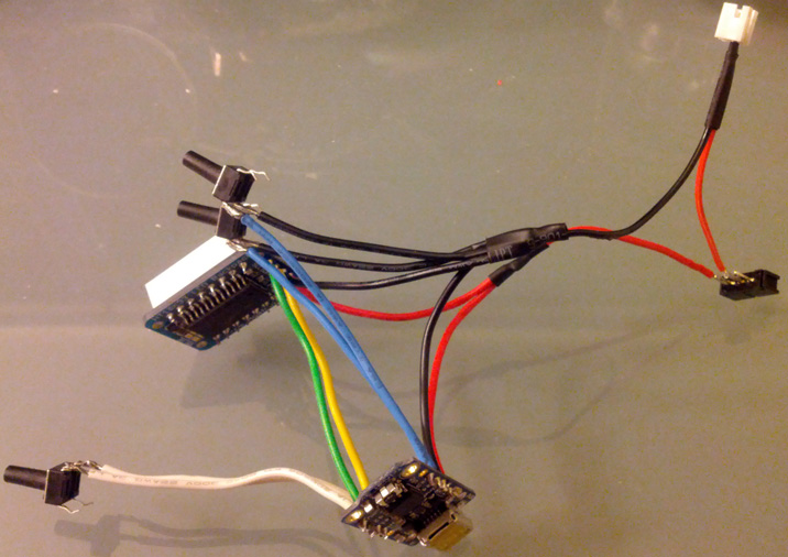
The complete wiring diagram for the device we'll be building is shown below. Refer to it often as you follow the wiring instructions.

- Take the Adafruit Mini 8x8 LED Matrix w/I2C Backpack out of its packaging.
- Place the LED matrix over the silkscreen side of the Backpack (the side that does not have the controller chip on it). The Mini 8x8 LED Matrix is symmetric, so it can go in either way, but I like to align the printed text on the LED matrix with the "From Adafruit" text on the Backpack. Again, do not cover up the controller chip!
- Solder the 16 pins of the LED matrix and clip the leads.
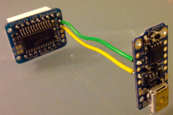
- Cut and strip two lengths of wire approximately 2 inches (5 cm) long. Solder one from the D/SDA pad on the Backpack to the #0 pad on the Trinket. Solder the other from the C/SCL pad on the Backpack to the #2 pad on the Trinket. (Corresponding to the yellow and green wires in the wiring diagram.)
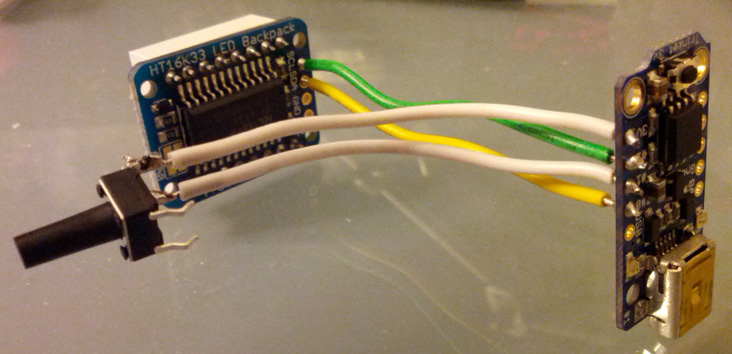
- Take three very tall tactile button switches out of their packaging.
- Cut and strip two lengths of wire, the same length as in step 4. Solder one from the #1 pad on the Trinket to one side of a button switch. Solder the other from the 3V pad on the Trinket to the other side of the same button switch. (Corresponding to the gray wires in the wiring diagram.)
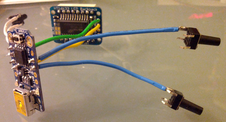
- Cut and strip two lengths of wire, the same length as in step 4. Solder one from the #3 pad on the Trinket to one side of the second button switch. Solder the other from the #4 pad on the Trinket to one side of the third button switch. (Corresponding to the orange and brown wires in the wiring diagram.)
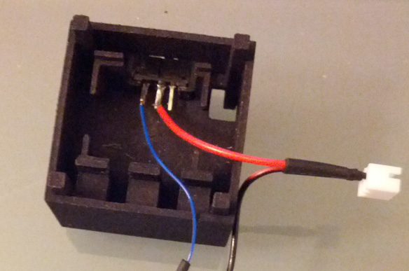
- Take one slide switch out of its packaging.
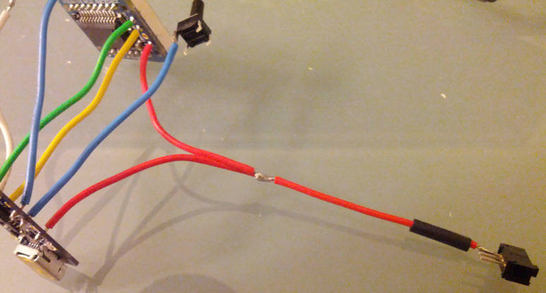
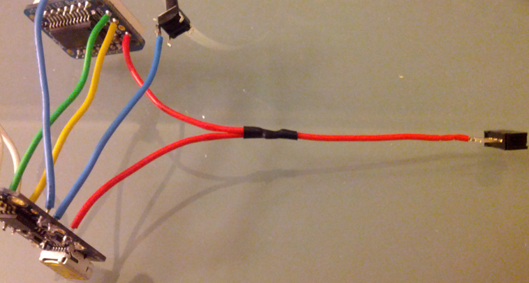
- Cut and strip three lengths of wire. Solder one to the +/VCC pad on the Backpack, one to the BAT+ pad on the Trinket, and one to an outer pin of the slide switch. (Corresponding to the red wires in the wiring diagram.)
- Slip a length of heat shrink onto the wire connected to the slide switch. Solder the three wires together.
- Slip the heat shrink over the soldered connection. Use a heat gun, lighter, or match to shrink the heat shrink.
- Take the JST extension cable out of its packaging.
- Cut the JST extension cable approximately 2 inches (5 cm) from the socket end (where the battery plugs in). Separate and strip the wires.
- Solder the red wire of the JST extension cable to the center pin of the slide switch.
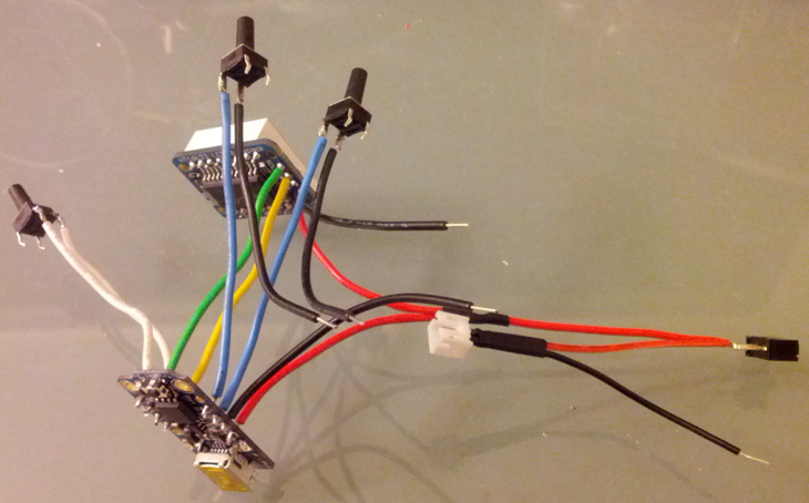
- Cut and strip four lengths of wire. Solder one to the −/GND pad on the Backpack, one to the GND pad on the Trinket, and the last two to the other sides of the button switches from step 7. (Corresponding to the black wires in the wiring diagram.)
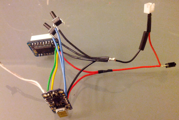
- Slip a length of heat shrink onto the black wire of the JST extension cable. Solder the five wires together.
- Slip the heat shrink over the soldered connection. Use a heat gun, lighter, or match to shrink the heat shrink.
- Double-check that the circuit in front of you matches the wiring diagram shown earlier.
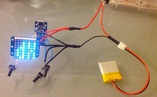
- Connect the 3.7v 150mAh Li-Poly battery to the JST extension cable.
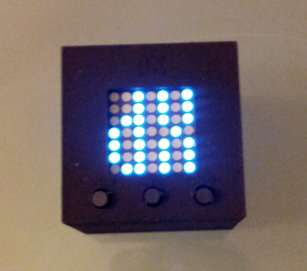
- Turn on the slide switch. The LED matrix should display the letters "dX" for about 10 seconds. Press the buttons to make sure they all respond. If everything checks out, you're done with wiring!


Assembly
- Turn off the slide switch and disconnect the battery.
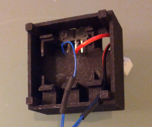
- Take the dX enclosure out of its packaging. Locate the middle piece.
- Insert the slide switch into its notch at the top of the enclosure. If necessary, file the edge of the switch's casing and/or the enclosure until the switch goes in.
- Feed the JST connector through the hole in the enclosure.
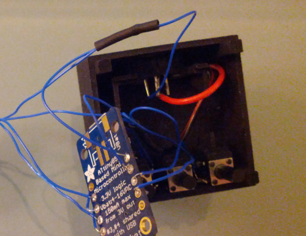
- Insert the button switches. Put the switch going to pin #1 on the left, the switch going to pin #3 in the center, and the switch going to pin #4 on the right. You may have to straighten out the unused pins on the #1 and #4 switches to get them to fit. Make sure the pins are not touching each other.
- Pack the Trinket and wiring into the center of the enclosure.
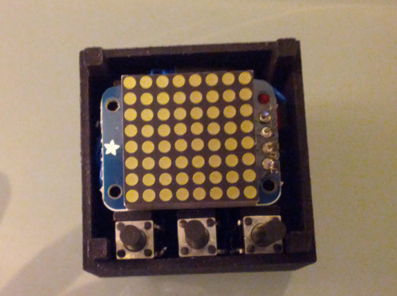
- Place the LED matrix on top with the Adafruit logo to the left.
- Install the faceplate.
- Connect the battery and install the backplate.
- Turn on the slide switch. Enjoy! Here is the instruction manual.