Create your own dX: Overengineered Electronic Die
Make your own dX: Overengineered Electronic Die! Here is how I made the second version using a custom PCB but not using a piezo sensor. (The first version used an Adafruit Trinket. I have since made a third version adding a piezo sensor.)
I used the following things:
- A standard or relatively-standard Arduino board.
- An Adafruit Mini 8x8 LED Matrix w/I2C Backpack in any color.
- The dX custom PCB.
- An ATtiny85 microprocessor.
- An 8-pin DIP socket.
- A Schottky diode.
- A 3.3v voltage regulator.
- Three 10μF capacitors. (One will be used during programming. The other two will be installed on the PCB.)
- Three very tall tactile button switches.
- A 4-pin female header. (If you can't find a 4-pin header, cut down a larger one.)
- Six 3-pin female headers. (If you can't find 3-pin headers, cut down larger ones.)
- One slide switch.
- A JST extension cable to cut in half to use as the battery connector.
- A 3.7v 150mAh Li-Poly battery.
- Hookup wire.
- A breadboard.
- A bunch of wires for breadboarding.
- The Adafruit Arduino 1.0.5 software. (It comes already hacked to support ATtiny and has the TinyWireM library pre-installed.)
- ATtiny microcontroller support for the Arduino IDE. (For bare ATtiny as opposed to Trinket.)
- The dX firmware for the custom PCB.
- The dX Enclosure for Custom PCB from Shapeways.
Programming
Before wiring dX, we'll have to program the ATtiny85 using an Arduino as an ISP. This is fairly complicated, but also fairly straightforward once you get past the 20 or so steps required. :)
- Download and install Adafruit Arduino 1.0.5. (You could also use the official Arduino IDE, but you would have to hack it to support ATtiny and install the Adafruit TinyWireM library yourself.)
- Download and unzip ATtiny microcontroller support for the Arduino IDE.
- Locate your Arduino sketchbook folder. Create a new folder called hardware inside the sketchbook folder, if it doesn't already exist.
- Copy the attiny folder (inside the attiny-master folder unzipped in step 2) into the hardware folder.
- Launch Adafruit Arduino 1.0.5.
- Open the ArduinoISP sketch from File → Examples → ArduinoISP.
- Connect your Arduino to your computer.
- Select your model of Arduino (or a compatible model) from Tools → Board → <model name>.
- Select the port corresponding to your Arduino from Tools → Serial Port → <port name>.
- Make sure the programmer is set to Tools → Programmer → AVRISP mkII.
- Upload the ArduinoISP sketch to your Arduino. (When I first tried this, I got a
java.lang.NoSuchMethodError: gnu.io.CommPortIdentifier.openerror. My solution was to use Arduino 1.5.5 instead, just for this step. This is not Adafruit's fault; the official Arduino 1.0.5 has the same issue.) - Disconnect the Arduino. (We're going to be hooking things up to it.)
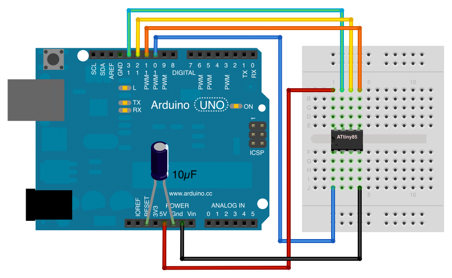
- Insert the ATtiny85 into the breadboard.
- Wire the Arduino to the ATtiny85. Connect Arduino 5V to ATtiny85 pin 8, Arduino GND to ATtiny85 pin 4, Arduino pin 10 to ATtiny85 pin 1, Arduino pin 11 to ATtiny85 pin 5, Arduino pin 12 to ATtiny85 pin 6, and Arduino pin 13 to ATtiny85 pin 7.
- Add a 10μF capacitor between Reset and Ground on the Arduino (not on the ATtiny85!). Make sure the side with the − stripe is the one connected to Ground.
- Download and open the dX_pcb sketch. (Now we're finally getting somewhere!)
- Connect your Arduino to your computer (again).
- Change the board setting to Tools → Board → ATtiny85 (internal 8 MHz clock).
- Change the programmer setting to Tools → Programmer → Arduino as ISP.
- Use Tools → Burn Bootloader to set the ATtiny85 to operate at 8 MHz.
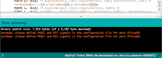
- Upload the dX sketch. After a while, you should see the "Done uploading" message. If you see a message about
avrdude: please define PAGEL and BS2 signals, you can safely ignore it. If you see any other errors, double-check your wiring and try again. - Pull the ATtiny85 off the breadboard. You're done with programming; on to wiring!
Wiring
Now with the ATtiny85 programmed, we can assemble the custom PCB.
- Take the Adafruit Mini 8x8 LED Matrix w/I2C Backpack out of its packaging.
- Place the LED matrix over the silkscreen side of the Backpack (the side that does not have the controller chip on it). The Mini 8x8 LED Matrix is symmetric, so it can go in either way, but I like to align the printed text on the LED matrix with the "From Adafruit" text on the Backpack. Again, do not cover up the controller chip!
- Solder the 16 pins of the LED matrix and clip the leads.
- Insert the four-pin header that comes with the Backpack into the breadboard. Place the Backpack on top and solder it to the header.
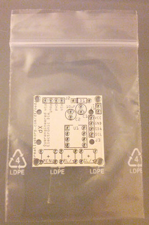
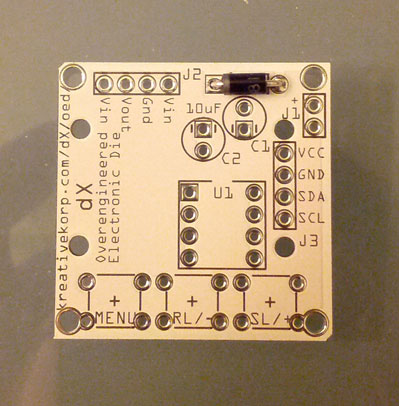
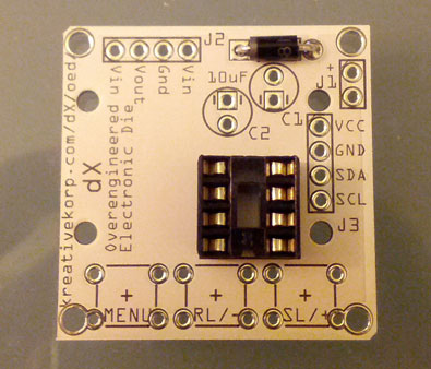
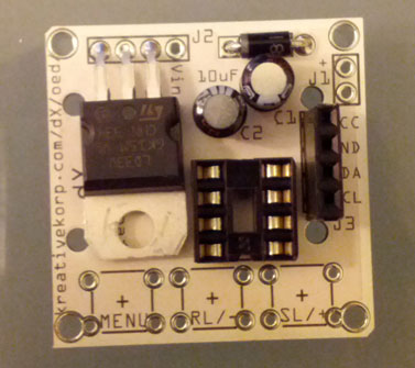
- Take the dX custom PCB out of its packaging.
- Insert the diode into D1 on the PCB, making sure the stripe on the diode is aligned with the stripe on the board.
- Solder in the diode and clip the leads.
- Insert the 8-pin DIP socket into U1 on the PCB and solder it in.
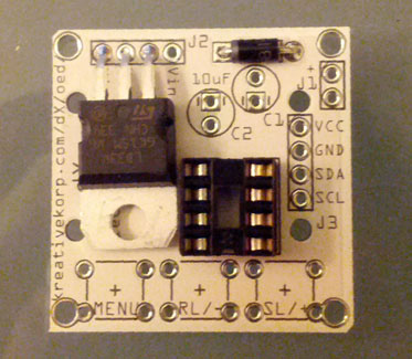
- Insert the 3.3v voltage regulator into J2 on the PCB, making sure the pins match the labels on the PCB. Double-check the datasheet to make sure. (The reason there are four holes for a three-pin part is because there are two possible pinouts for a voltage regulator.) Solder it in and clip the leads.
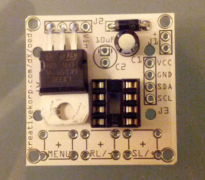
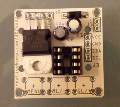
- Insert a 10μF capacitor into C1 on the PCB, making sure the − stripe is aligned with the − sign on the board. Solder it in and clip the leads.
- Insert a 10μF capacitor into C2 on the PCB, making sure the − stripe is aligned with the − sign on the board. Solder it in and clip the leads.
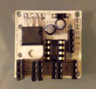
- Find or cut off a female header with 4 pins.
- Insert the 4-pin female header into J3 on the PCB and solder it in.
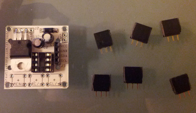
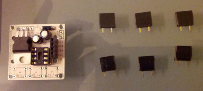
- Find or cut off six female headers with 3 pins each.
- Remove the center pin from each 3-pin female header.
- Insert the 3-pin headers (with the center pin removed) into the switch contacts on the PCB, oriented vertically. Solder them in.
- Take one slide switch out of its packaging.
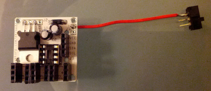
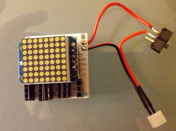
- Cut and strip a length of wire approximately 2 inches (5 cm) long. Solder one end to the pin marked + on J1 on the PCB. Solder the other end to an outer pin of the slide switch.
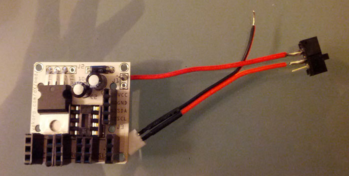
- Take the JST extension cable out of its packaging.
- Cut the JST extension cable approximately 2 inches (5 cm) from the socket end (where the battery plugs in). Separate and strip the wires.
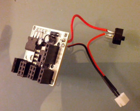
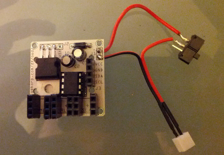
- Solder the red wire of the JST extension cable to the center pin of the slide switch.
- Solder the black wire of the JST extension cable to the other pin on J1 on the PCB.
- Insert the ATtiny85 into the 8-pin DIP socket, making sure the notch faces upward.
- Insert the LED matrix into the 4-pin header with the Adafruit logo to the left.
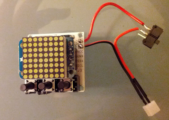
- Take three very tall tactile button switches out of their packaging.
- Insert the button switches into the 3-pin headers.
- Connect the 3.7v 150mAh Li-Poly battery to the JST extension cable.
- Turn on the slide switch. The LED matrix should display the letters "dX" for about 10 seconds. Press the buttons to make sure they all respond. If everything checks out, you're done with wiring!


Assembly
- Turn off the slide switch and disconnect the battery.
- Take the dX enclosure out of its packaging. Locate the middle piece.
- Insert the slide switch.
- Feed the JST connector through the hole.
- Place the PCB on top with the button switches on the bottom.
- Install the faceplate.
- Connect the battery and install the backplate.
- Turn on the slide switch. Enjoy! Here is the instruction manual.